How to Calibrate an Analyzer in Process Analyzer Systems
How to Calibrate an Analyzer in an Analytical Instrumentation System
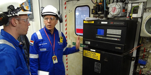
Tony Waters, Sampling Systems Expert and Instructor
In many analytical instrumentation systems, the process analyzer does not provide an absolute measurement. Rather, it provides a relative response based on settings established during calibration—a critical process subject to significant error. To calibrate a process analyzer, calibration fluid of known contents and quantities is passed through the analyzer, producing measurements of component concentration. If these measurements are not consistent with the known quantities in the calibration fluid, the process analyzer is adjusted accordingly. Later, when process samples are analyzed, the accuracy of the analyzer’s reading will depend on the accuracy of the calibration process.
It is imperative that we understand how error or contamination can be introduced through calibration; when calibration can—and cannot—address a perceived performance issue with the process analyzer; how atmospheric pressure or temperature fluctuations can undo the work of calibration; and when and when not to calibrate.
System Design
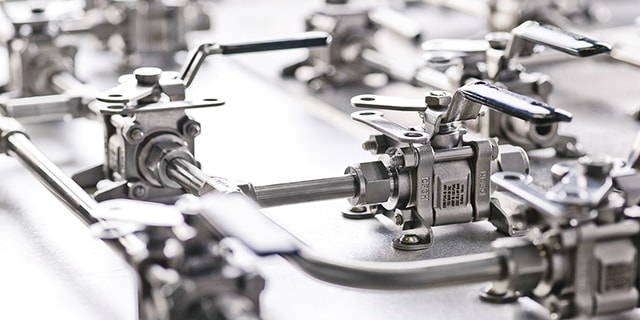
One common problem in calibration is inadequate selection system design. In many cases, the calibration fluid is introduced downstream of the stream selection valve system and without the benefits of a double block and bleed (DBB) configuration demonstrated in Figure 1. A better place to introduce the calibration fluid would be through the sample stream selection system, as in Figure 2. The purpose of a sample stream selection system is to enable rapid replacement of sample streams without the risk of cross contamination. In Figures 1 and 2, each stream in the sample stream selection system is outfitted with two block valves and a bleed valve to ensure that one stream — and only one stream — is making its way to the analyzer at one time.
Over the years, stream selection systems have evolved from DBB configurations comprised of conventional components to modular, miniaturized systems. The most efficient systems provide fast purge times, low valve actuation pressures, and enhanced safety characteristics, together with high flow capacity and consistent pressure drop from stream to stream for a predictable delivery time to the analyzer.
A stream selection system provides the greatest insurance against the possibility of the calibration fluid leaking into a sample stream. Nevertheless, some technicians will bypass this assembly and locate the calibration fluid as close as possible to the analyzer with the intent of conserving the fluid. If only a single ball valve is used, as shown in Figure 1, the attempt to conserve calibration gas may result in biased analyzer readings. The analyzer may be properly calibrated, but there is always the risk that a small amount of calibration gas could leak into the sample stream and throw off the measurements.

Figure 1. In this configuration, calibration gas is introduced downstream of the stream selection system without the benefits of a DBB assembly.

Figure 2. As shown in this configuration, the calibration gas is best introduced through the sample stream selection system, where a DBB assembly guards against the risk of contamination.
In some applications, the United States Environmental Protection Agency (EPA) requires that the calibration fluid be introduced at an early point in the sampling system, usually near the probe. The reasoning is that the calibration fluid should be subjected to all the same variables as the sample stream. This makes sense, as this setup will provide a fair estimate of the amount of time it takes for a sample to travel from the probe to the analyzer. Generally speaking, that period of time is often underestimated or unknown.
However, a relatively large quantity of calibration fluid is required if it is to run through the entire sampling system. It is not surprising that many facilities cannot use this option. A good compromise is to run the calibration fluid through the stream selection system, dedicating one stream to the fluid. This configuration provides the calibration fluid with the best chance of reaching the analyzer without being contaminated by the sampling streams. When not in use, the two block valves will prevent the fluid from contaminating the sample streams. With miniature modular platforms, the amount of calibration fluid required will be minimal.
Limitations of Calibration
To effectively calibrate an analyzer, the operator, technician, or engineer should understand, theoretically, what calibration is, what it can correct, and what it cannot.
A process analyzer must be precise. It must yield repeatable results when presented with a known quantity in the form of a calibration fluid. If the process analyzer does not return repeatable results, either the analyzer is malfunctioning, or the system is not maintaining the sample at constant conditions. Calibration cannot correct for imprecision.
If the process analyzer produces consistent results but the results are not the same as the known composition of the calibration fluid, the analyzer is said to be inaccurate. This situation can and should be addressed through calibration. This is called correcting the bias.
However, even if the process analyzer is found to be precise and accurate when tested with calibration fluids, it is still possible that it will yield inaccurate results when analyzing the sample stream. If the analyzer is asked to count red molecules and it encounters pink ones, what does it do? The pink molecules look red to the analyzer, so it counts them as red, resulting in an inflated red count. This is called positive interference. For example, in a process analyzer system designed to count propane molecules, propylene molecules may show up. It’s possible that the analyzer will count them as propane because it was not configured to make a distinction between the two.
No process analyzer is perfect, but they all are built for selectivity. Some process analyzers are more complex and are programmed to chemically inhibit certain types of interference. For example, a total organic compound (TOC) analyzer is designed to measure carbon content in wastewater so it can be determined if hydrocarbons are being disposed of inappropriately. To do so accurately, the process analyzer removes a source of positive interference — inorganic carbons, like limestone—which is present in hard water. Without this initial step, the process analyzer would measure both organic and inorganic carbon, confusing hydrocarbons with hard water.
Another type of interference is negative interference: A molecule that should be counted is not counted because another molecule is hiding it. For example, in fluorinated drinking water, an electrode is used to analyze the amount of fluoride in the water. However, hydrogen ions, which are common in drinking water, hide the fluoride so the count is inaccurately low. The analyzer may read 1 ppm, which is a standard dose but, in fact, the water may contain 10 ppm. The solution is to remove the source of interference. By introducing a buffer solution, the hydrogen ions are removed, and the electrode can accurately measure the fluoride.
With an understanding of positive and negative interference, as well as precision and accuracy, we begin to grasp the formidable challenges we face in enabling process analyzers to yield desired results. There is an easy assumption that if the process analyzer is not producing the desired result, calibration is the answer. But as we have just seen, calibration has its limitations and cannot solve all problems.
Controlling for Atmospheric Changes in Gas Analyzers
Gas analyzers are essentially molecule counters. When they are calibrated, a known concentration of gas is introduced, and the process analyzer’s output is checked to ensure that it is counting correctly. But what happens when the atmospheric pressure changes by 5 to 10 percent as it is known to do in some climates? The number of molecules in a given volume will vary with the change in atmospheric pressure and as a result, the analyzer’s final count will change.
There is a common misperception that atmospheric pressure is a constant 14.7 psia (1 bar.a), but, based on the weather, it may fluctuate as much as 1 psi (0.07 bar) up or down. In order for the calibration process to be effective, absolute pressure in the sampling system during calibration and during analysis of samples must be the same. Absolute pressure may be defined as the total pressure above a perfect vacuum. In a sampling system, it would be the system pressure as measured by a gauge, plus atmospheric pressure.
If pressure is so critical, how does one control for it? Some process analyzers, especially infrared and ultraviolet, allow atmospheric pressure to affect the reading but then later correct for it electronically. However, many process analyzers, including many gas chromatographs, do not correct for atmospheric pressure fluctuations. In fact, most systems do not correct for pressure fluctuations and many system engineers or operators ignore them. Some believe that atmospheric fluctuations are not significant. Others maintain that any atmospheric fluctuations are compensated for by other related or unrelated variables affecting the process analyzer. Nevertheless, atmospheric fluctuations can be significant. Let’s suppose that when you calibrate your process analyzer, the atmospheric pressure is X, but, later, when you inject the process gas, the atmospheric pressure is X + 1 psi (0.07 bar). The answer may be as much as 7 percent off the measured value.
With environmental regulations, most process analyzer systems now vent to flare stacks or other return points. Since pressure fluctuations from such destinations will affect pressure upstream in the analyzer, there are vent systems, equipped with eductors and regulators, designed to control for these fluctuations. Unfortunately, these systems employ regulators that are referenced to atmosphere. As a result, while these systems control for fluctuations from the vent, they do not control for fluctuations in atmospheric pressure.
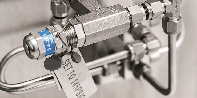
For such a system to control for atmospheric as well as vent pressure fluctuations, an absolute pressure regulator is required. Unlike a normal regulator, an absolute pressure regulator is not comparing pressure inside the system to pressure outside the system, which is itself fluctuating according to the weather. Rather, it is comparing pressure inside the system to a constant set pressure that does not fluctuate at all (or very little). Often, this set pressure is actually 0 psia (0 bar.a).
Validation versus Calibration
The best method for calibration is one that employs an automated system of regular validation, with statistical interpretation. Validation is the process of checking the analyzer at regular time intervals to determine whether it is on or off target. In validation, a reading is taken, and that reading is recorded. It is the same process as calibration, except that no correction is made.
An automated system will run a validation check at regular intervals, usually once a day, and analyze the outcome for any problem that would require an adjustment or recalibration. The system will allow for inevitable ups and downs, but if it observes a consistent drift in the measurements — one that is not correcting itself — then it alerts the operator that the system could be going wrong.
A person can manually validate a system at regular intervals, just like an automated system, but, more often than not, that person will also make an adjustment to the analyzer, even if the system is just 1 percent off. The result is a series of occasional and minor adjustments that introduce additional variance and make it difficult to analyze trends and determine when the system is truly running off course. It is better to allow an automated system to run unattended until a statistical analysis of the results suggests that attention is required.
Conclusion
Calibration is an important process and an absolute requirement in analytical systems, but care must be taken to perform this process properly. The operator, technician, or engineer should understand how best to introduce the calibration gas into the system and how to control for atmospheric fluctuations in gas analyzers. Further, the technician or operator should understand the limitations of calibration — what problems it can address and what problems it cannot — and how frequent adjustments to the analyzer based on single calibrations introduce error. If the process analyzer is regularly validated with an automated system and is properly calibrated when a statistical analysis justifies it, calibration will function as it should, and provide an important service in enabling the analyzer to provide accurate measurements.
Related Articles
How to Isolate Industrial Fluid Systems with Block Valves
The isolation of industrial fluid system lines prior to maintenance is vital to plant safety. One of the safest ways to isolate a fluid system line is to install two block valves. Learn how to design proper configurations for your system.
Why Haven’t Sampling Systems Improved — Three Main Reasons
The past 50 years, process analyzers have vastly improved— but sampling systems have not. Luckily, most issues are due to human error & can be corrected with proper training. Learn three reasons why sampling systems fail & solutions for your plant.