Tips to Maintaining a Representative Sample in an Analytical Instrumentation System
Tips to Maintaining a Representative Sample in an Analytical Instrumentation System
The objective of an analytical instrumentation (AI) system is to provide a timely analytical result that is representative of the fluid in the process line at the time the sample was taken. If the sample is altered by the configuration of the AI system so that the analytical result is different, the sample is no longer representative, and the outcome is no longer meaningful or useful. Assuming the sample is properly taken at the tap, it may still become unrepresentative under any of the following conditions, if:
- Deadlegs (or dead spaces) are introduced at inappropriate locations in the process control system, resulting in a “static leak,” a bleeding or leaking of the old sample into the new sample
- The sample is altered through contamination or adsorption
- The balance of chemicals is upset due to a partial change in phase
- The sample undergoes a chemical reaction
Understanding Deadlegs
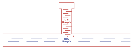
It’s important to understand the difference between mixing volumes and deadlegs. A mixing volume is a reservoir with a separate inlet and an outlet, such as a filter or knockout pot. Fluid flows, often slowly, through a mixing volume. A deadleg, on the other hand, is typically a tee formation with a block at the end so there is no through-flow (see Figure 1).
Figure 1. In this deadleg configuration, old sample trapped in the tee formation leaks into the main fluid stream, contaminating the new sample.
Examples of deadlegs include pressure gauges, transducers, lab sampling valves, or relief valves. You can calculate the rate at which a mixing volume will flush out an old sample but the same is not true of a deadleg. A deadleg holds the old sample, allowing a small portion of it to mix with the new sample and contaminating it.
Deadlegs may eventually dissipate without intervention—or not. They do not behave in a predictable manner. Generally, deadlegs become more problematic as the ratio of length to diameter increases. In addition, lower flow in the analytical line increases the degree of the deadleg’s effect. A pressure gauge with a deadleg volume of 10 cm3 may not have much effect in high flow, but in low flow (e.g., 30 cm3/min) it could—if located in the wrong place—compromise the whole application.
Here are some general guidelines concerning deadlegs:
- Use high flow rates whenever possible
- Select a component design that minimizes or eliminates deadlegs
- When installing the component, ensure that the end connection minimizes the length of the deadleg
- Remove deadlegs to the bypass loop, so only the minimal number of deadleg components are on the direct line with active flow to the analyzer
- Replace a tee and two-way ball valves with three-way ball valves
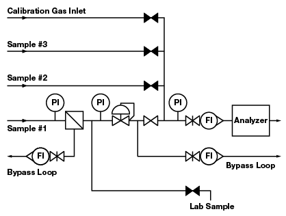
Figure 2. Five deadlegs in this configuration pose the risk of contaminating the sample.
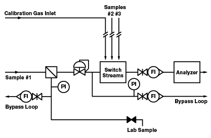
Figure 3. A variation of Figure 2, this configuration introduces design improvements that eliminate the deadlegs or move them to locations where they will not have an effect on the analyzer reading.
In most process control systems, deadleg components can be positioned so that most are not in a direct line with active flow to the analyzer. Deadleg components can be placed on a bypass loop and will still serve their intended purpose. A bypass loop (or fast loop) is a configuration that enables relatively fast flow in a loop with a return to the process line. At one point in the loop, a part of the flow is diverted to the analyzer. Figure 2 shows a system with five deadlegs. Figure 3 shows a variation of this configuration with the following improvements:
- Two pressure gauges are removed to a bypass loop
- One pressure gauge is removed without a replacement
- The calibration gas inlet is moved to the stream selection system
- The lab sample take-off is moved to a flow loop that originates at a filter
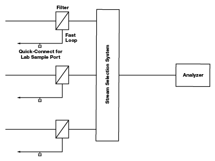
When multiple fluid streams are running to the same analyzer through a stream selection system, components with deadlegs should, if at all possible, be placed before the stream selection system in a bypass or return line to minimize the opportunity for cross-stream contamination. The same is true of components with “memory,” i.e., components with a lot of surface area (filters) or with permeable materials like elastomers. For example, rather than locating one filter after the stream selection system, it is better to purchase multiple filters and locate them before the stream selector system—one in each of the multiple lines. Similarly, it is not advisable to locate a lab sample port, with a tee and quick-connect, after the stream selection system because the tee configuration is a deadleg that may cause cross-stream contamination.
Figure 4. Quick-connect lab sample ports are located on bypass loops before the stream selection system. This way they are not creating deadlegs on a line shared by sample streams.
An ideal configuration, as shown in figure 4, places the lab sample port on a bypass loop—a separate bypass loop for each sample line—before the stream selection system. The lab sample port, gauges and other deadlegs can be located on the bypass loop, downstream of the point where flow is diverted to the analyzer. An additional advantage to this configuration is that while one stream is running to the analyzer, the other streams continue to flow through their respective bypass loops, keeping the sample current. Components with limited memory, those that can be safely located after the stream selection system, include some high-quality regulators, shutoff valves, check valves and flow meters. In the case of liquid samples, when there is minimal pressure drop through the analyzer, deadleg components like gauges may be located after the analyzer.
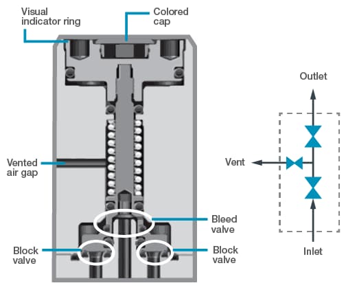
Using a double block and bleed (DBB) configuration , which consists of two block valves and a bleed valve running to a vent, is a well-established standard in the industry – and for good reason: It guards against contamination between fluid streams. This configuration should be used whenever there is an intended block between two fluid streams that must remain separate. DBB is the basis of all stream selector systems.
Beyond component placement, component selection is also an important factor in process control system design. Components vary in the amount of dead space they contain. The system designer should review cutaway drawings and look for dead space. The flow path through a valve or an assembly of components should be smooth and without sharp changes in direction, which may cause pressure to drop.
Leaks and Permeation
Leaks and permeation occur in the direction of lower partial pressure. To determine whether leaks or permeation will be an issue for a system, identify the sample composition and its absolute pressure, and do the same for the atmosphere outside the system. From there, determine partial pressure. For example, if the system media is 100 percent nitrogen at 100 psia, then the partial pressure of the nitrogen is 100 psia. And if, for simplicity’s sake, we say the atmosphere is 80 percent nitrogen and 20 percent oxygen at 15 psia, then the partial pressure will be nitrogen 12 psia and oxygen 3 psia. Given these conditions, oxygen will leak into the system and nitrogen will leak out of the system. Even if the system pressure were increased to 200 psia, 1000 psia or higher, oxygen from the atmosphere would still leak in because the partial pressure for oxygen is greater outside the system than inside the system.
Permeation is not always an issue. A small amount of oxygen leaking into the sample may not matter, depending on the application. When permeation is a potential issue, the system designer should avoid O-rings, elastomers, and PTFE and, instead, employ stainless steel and metal-to-metal seals wherever possible. Another possibility is to enclose the sampling conditioning system or other parts of the system in a nitrogen-purged box.
Design configurations of some pneumatic valves allow for leaks or permeation between the sample and the actuation air. A valve’s actuator may be integral to the valve design, as in miniature modular valves. In other words, the valve body and the actuator are contained in the same block, and they may be separated by only a single seal, such as an O-ring. If this single seal were to fail, molecules from the pneumatic air could leak into the sample, or molecules from the sample may escape into the actuation air. Such leaks may lead to a bad analytical reading or, worse, could cause a fire or an explosion. When employing actuators integral to the valve design, look for valves with double seals as well as safety provisions, such as a vented air gap, which allows air or process leaks to safely escape (Figure 5).
Figure 5. In this drawing of a double block and bleed valve, double seals and a vented air gap guard against the possibility of actuation air leaking into the fluid stream.
Adsorption
Adsorption refers to the tendency of some molecules to stick to solid surfaces, including the insides of tubing. Some molecules, like nitrogen, oxygen and other “permanent gases,” stick to solid surfaces but are easily knocked off. Other molecules, like water and hydrogen sulfide, stick to tubing and hold tight. If one of these sticky molecules is in the sample, it will stick to the inside surface of the tubing and will not show up in the analytical reading for some time.
Some operators believe once the insides of the tubing have been saturated, the problem of adsorption goes away but this is not true. Suppose the temperature of the tubing increases, as a result of daily changes in the sun’s intensity. Higher temperatures give molecules more energy, so that they leave the walls of the tubing and cause changes in the analytical reading.
If the molecules being measured make up more than 100 ppm in your sample, adsorption will probably not matter a great deal. However, if the molecules being measured make up less than this amount, adsorption must be addressed. An electropolished surface on the inside of the tubing, or PTFE lining, will provide marginal improvements in the adsorption rate. Another option is silicon-lined tubing. During manufacturing, a very thin coating of silicon is deposited on the inside of the tubing. While the product is expensive, the rate of improvement is dramatic. The tubing is still flexible with the silicon lining, although the minimum bend radius is increased.
Phase Preservation
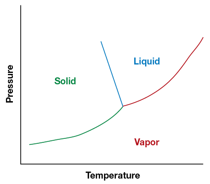
Maintaining a representative sample requires avoiding a partial phase change in the sample. Molecules assume different phases – solid, liquid, gas or a mixture— depending on temperature and pressure in the system. The point at which the phases begin to change for each molecule is different, as represented in phase diagram, with temperature along one axis and pressure along the other. Figure 6 shows below the composition of water. Solid lines show the interfaces between the phases.
Figure 6. The phase change chart shows the points where water changes between a solid, a liquid and a gas.
An analytical sample usually consists of more than one type of molecule. It is important to determine the composition of the sample, (i.e., what percent consists of molecule A, what percent consists of molecule B, etc.).
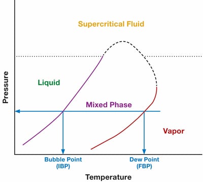
As long as the sample remains all liquid or all gas, the composition will remain the same. However, if we allow a partial phase change of the sample, our composition will change. Figure 7 below shows a phase chart for a mixture of molecules. At any point between these liquid and vapor phase, there will be a two-phase combination—resulting in different compositions. In other words, the sample has fractionated into two different compositions, and the analyzer can no longer determine what the original composition was.
Figure 7. Phase chart for a mixture of molecules
The challenge before the analyzer engineer and technician is to maintain pressure and temperature in zones that will preserve the entire sample in one phase throughout the analytical system. For a gas sample, the simplest solution is to install a regulator, which will lower the pressure. In addition, if necessary, the sample lines can be heated and maintained at the high temperature with insulated, bundled tubing. Both regulators and bundled tubing are fairly easy components to install and maintain.
For liquid samples, the challenges are somewhat greater. A pump can raise the pressure and, if necessary, chillers may be installed. Unfortunately, neither pumps nor chillers are especially easy components to install and maintain, although they may be necessary.
Conclusion
Maintaining a representative sample can be challenging. There is no alarm that goes off in an analytical instrumentation system announcing that the sample is unrepresentative. The only way to uncover the problem is to be familiar with the points at which the sample system can falter. Fortunately, each of these issues are avoidable or correctable. Most corrective actions can be summarized as follows:
- Knowing the component design and its limitations (deadlegs, dead spaces, leaking of actuation air)
- Asking the right questions of the fluid system provider (e.g., about valve pressure ratings, cutaway drawings, and purgeability data)
- Placing components in the right location in the process control system (e.g., in the bypass loop, on one side or the other of the stream selection system)
- Determining/calculating if adsorption will happen or matter (based on partial pressure)
- Knowing which materials or designs will prevent leaks, permeation, and adsorption
- Calculating and maintaining the proper pressure and temperature for phase preservation, based on phase charts
Does your plant or facility require additional support to maintain representative samples with your analytical instrumentation systems? Learn how to troubleshoot common sampling system errors with Swagelok’s Sample System Problem Solving and Maintenance (SSM) training course. Contact your local sales and service center to register your team.
Images © 2013 “Industrial Sampling Systems”Related Articles
Sampling Systems: 8 Common Process Analyzer Accuracy Challenges
Sampling systems expert and veteran industry instructor Tony Waters offers plant managers and design engineers tested ways to identify and resolve 8 common challenges for process analyzer accuracy.


