Impulse Line Best Practices

Process Measurement – Impulse Line Best Practices
When measuring pressure, flow or level within your process, safety and accuracy are always the focus. From the tap to the transmitter, process measurement accuracy depends on the proper function of each component within the process instrumentation measurement loop. And while engineers and technicians often dedicate most of their attention to the transmitter, it is only as accurate as the impulse line inputs provided to it.
It is often hard to know when a process instrumentation line is not performing well. If your attention is focused solely on the transmitter, any possibility of success is undermined if the impulse line is the cause of poor performance.
Remaining educated about the possible issues within a process impulse line, including those related to overall design and layout, is necessary to the accuracy of your final measurement. This blog post will provide engineers and technicians alike with proven best practices to manage the success of their process impulse lines.

A standard diagram of a process measurement impulse line
Material Selection
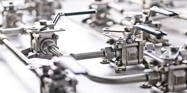
For each of the basic building blocks in a process instrumentation line – Process Interface Valves (PIVs), impulse lines and manifolds – there are critical choices in terms of materials that can affect accuracy.
Process media, environmental conditions, and system pressure/temperature often determine alloy selection. Stainless steel, or a higher metal alloy, is strongly preferred in most applications because it resists corrosion. However, many industrial plants continue to use carbon steel for process interface valves, piping and even for some manifolds. In certain low-moisture applications, carbon steel is acceptable, but for most other applications, it can be a risk. The scaling that commonly builds up on carbon steel can break away, flow downstream, lodge in a valve seat and obstruct a positive shutoff. The result is an inaccurate transmitter calibration or an inaccurate transmitter reading. If you employ carbon steel components in the instrument loop, they will require very close monitoring to ensure that scaling is not affecting the operation of the valves in the system. You can learn how to select the proper corrosion-resistant material for your specific application with materials science training from Swagelok.
Simplified Maintenance through Standardization
If your goal is standardization of design, there are established best practice configurations which can be implemented. While engineers have developed a multitude of design variations over time, many of them are not ideal for reliability and accuracy. Each system has different needs in terms of maintenance, and this increases complexity for maintenance teams.
Ideally, all process measurement systems should be designed using a consistent set of criteria, including establishing budgets and allowances for downtime, maintenance and accuracy. The optimum result often includes a high degree of standardization. For example, before standardization, a refining plant may have 30 different configurations for process instrumentation lines. After standardization, the same plant may have only six, with each containing the same basic components: a transmitter mount, manifold system and isolation valves. The primary variations might be the tubing runs and the type of isolation valves (DBBs, Gage root, etc.) which in turn depend upon the media, temperature, pressure and location of the transmitter or gauge.
With standardization, many things become simpler, including maintenance, installation, training and diagnostics. Reliability is also increased. Additionally, the facility can stock fewer replacement parts, reducing overhead costs.
Process Interface Valve (PIV)
The process interface valve is the first valve off the process line. Historically, the PIV of choice has been a single gate valve or ball valve. Both continue to be used today, especially in the U.S., but the best practice is a double block-and-bleed (DBB) valve, which consists of two isolation valves and one bleed valve in between.
The main reason for employing a DBB valve is safety. If you need to shut down the process instrumentation line for maintenance, you would close both block valves and open the bleed valve. If for any reason the first block valve were to leak, the second block valve would prevent pressure or fluid buildup in the process instrumentation line.
A double block-and-bleed configuration can be fabricated and assembled from three separate valves or can be purchased as a single, self-contained unit—reducing size and weight. The innovative self-contained DBB design is appropriate for all fluids, but especially for those with higher viscosity when using ball valves.
Impulse Lines
Impulse lines connect the PIV valve to the manifold and transmitter. Their purpose – the same as with all process instrumentation components – is to convey the precise process conditions to the transmitter. When laying out impulse lines, three main objectives come into play:
- Prevent corrosion or scaling, or plugging
- Reduce leak points
- Maintain temperature within a certain range or provide freeze protection
The first two objectives are best achieved by using tubing and tube fittings made from an appropriate alloy, such as stainless steel, as opposed to carbon steel pipe and threaded connections. Stainless steel tubing can be bent and shaped, which reduces the number of mechanical connections. When connections are necessary, two-ferrule, mechanical-grip type tube fittings will not back off with thermal cycling or vibration, unlike traditional tapered pipe threaded fittings.
The third objective – maintaining temperature within a certain range – is achieved by heating the impulse lines. You can insulate your impulse lines manually by field tracing or by purchasing tubing that has already been insulated and encased in a polymeric jacket. Pre-insulated bundled tubing comes ready to install in coiled lengths. It is important with pre-insulated tubing bundles to follow the manufacturer’s instructions for sealing the insulation when splicing or cutting the bundle.
Manifold
The manifold consists of a set of valves whose bodies are machined from a single block of metal, usually stainless steel. The manifold mounts to the transmitter and serves a critical function, enabling isolation for calibration or service of the transmitter.
Quality and reliability is especially important in a manifold. During calibration or normal operation, at least one of the valves in the manifold is in the shutoff position. If the shutoff is less than complete, the result can be an inaccurate reading from the transmitter.
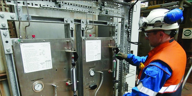
Does your facility require assistance identifying issues within your process instrumentation line? Experienced Swagelok field engineers will visit your facility, evaluate your systems and advise on enhancements that will improve your operations.
The Close Couple Manifold – An option
Now that we’ve reviewed the process instrumentation line in detail, let’s look at an option to further simplify the design. It’s an elegantly simple solution, if your application allows you to employ it.
Impulse lines can be costly to install and maintain, with challenges like clogs, leak points, temperature control and corrosion. The option – dubbed the “close couple” – eliminates the impulse lines. The process interface valve and manifold become one unit, and the transmitter mounts directly to it. Hence, the entire assembly attaches to the process line. While many engineers like this solution, close couple installations have their limitations.
One limitation is temperature. The reason for the traditional setup with impulse lines is to protect the transmitter from the high temperature of the process line. If the process line is too hot, the transmitter may not be able to operate only a few inches away in a close coupled installation.
A second limitation is access. If you need to get to the transmitter for calibration, it needs to be accessible, therefore mounting a close couple on a process location 50 feet in the air is not viable.
The final obstacle is initial cost. Close coupling requires an upfront investment, but in the long run the solution may be less costly overall. If you have an opportunity to employ this shortcut, we recommend using it.
Conclusion
If you value accurate measurements and invest in a premium transmitter, then your process instrumentation lines require the same level of attention. Process measurement accuracy is as dependent on the transmitter as it is on the quality of the process measurement line components, including how they are installed and maintained. Standardizing your facility on a core set of instrumentation hook up and process impulse line details, along with reliable system components will increase the reliability and accuracy of your measurement. More accurate measurements will yield welcome dividends in terms of time, efficiency, and plant profitability.
Related Articles
How to Isolate Industrial Fluid Systems with Block Valves
The isolation of industrial fluid system lines prior to maintenance is vital to plant safety. One of the safest ways to isolate a fluid system line is to install two block valves. Learn how to design proper configurations for your system.
Sampling Systems: 8 Common Process Analyzer Accuracy Challenges
Sampling systems expert and veteran industry instructor Tony Waters offers plant managers and design engineers tested ways to identify and resolve 8 common challenges for process analyzer accuracy.
4 Strategies to Maximize Industrial Fluid System Efficiencies
Like most plant managers and engineers, you have a lot of responsibilities—but not all the resources you need to run your plant safely and efficiently. Learn how to maximize throughput, reduce costs and avoid downtime while managing your fluid system.